Introduction and Project Background
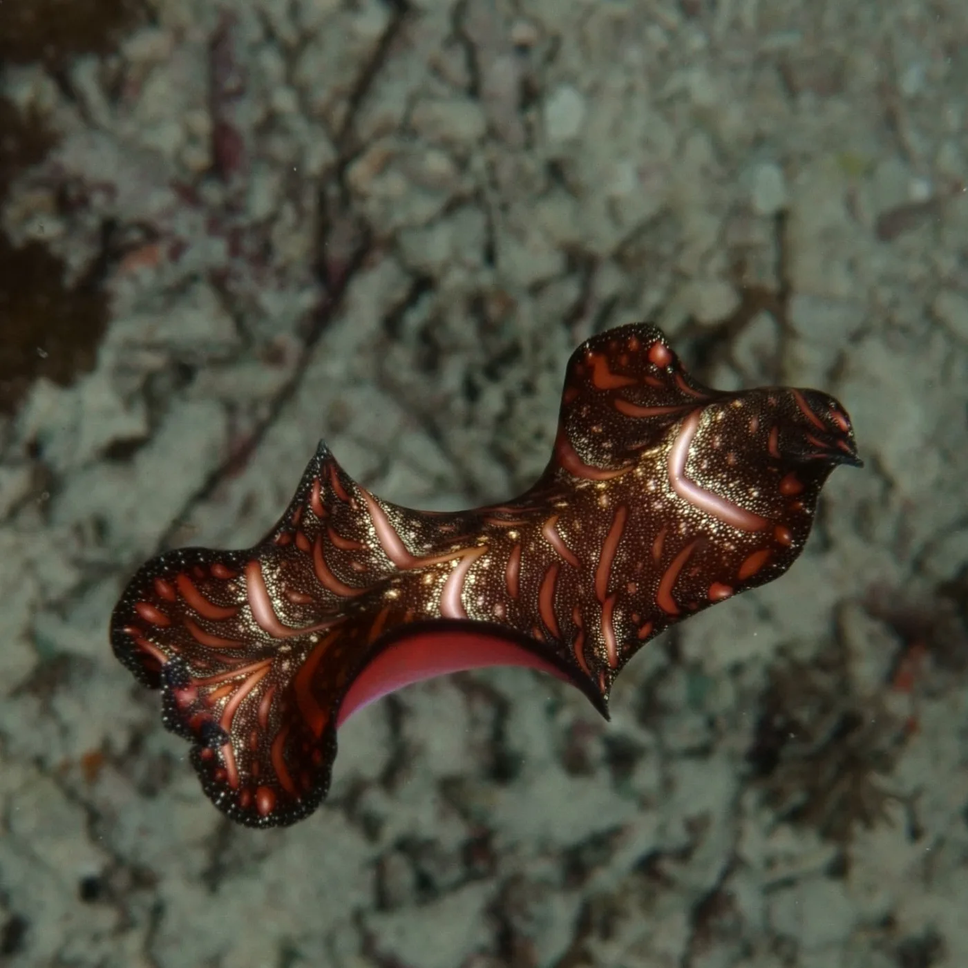
Persian carpet flatworms (Pseudobiceros bedfordi), also described as a “magic carpet,” evolved to swim by undulating the ruffled margins of their thin bodies. They also typically crawl on the seafloor using such undulating motion. When tasked with creating a mechanically-driven amphibious vehicle, the team decided to take on this bio-inspired approach.
We are simplifying the traditional undulating fin robot design by utilizing a central camshaft instead of a large number of servos. Below are two examples of previous undulating fin robots that utilize more robust motor control rather than pure mechanical power transmission.
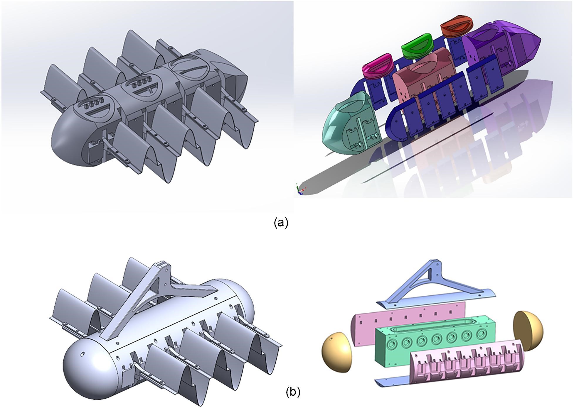
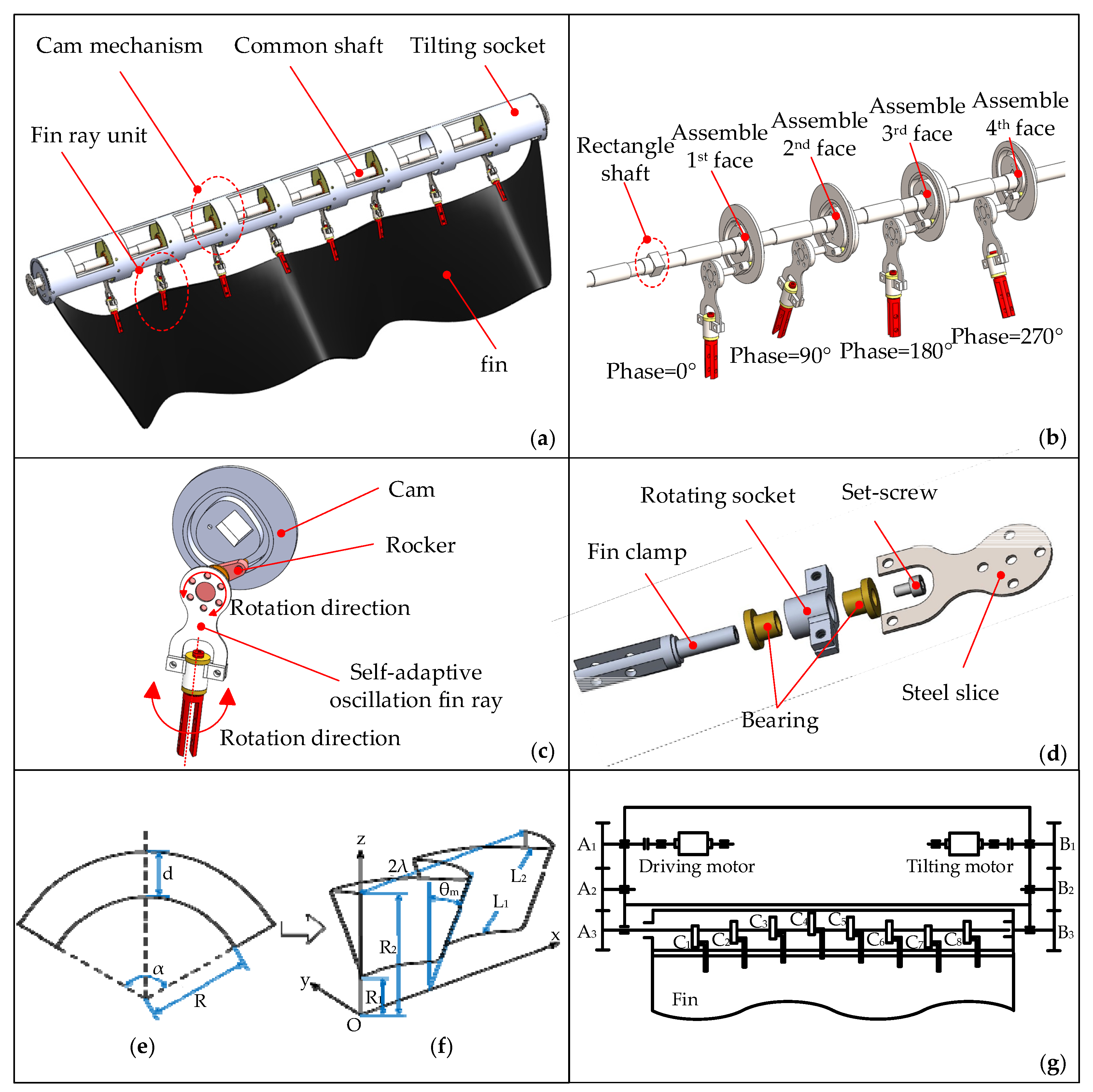
We follow a similar structure to the figure shown below, where we chose to utilize a common CAM shaft that drives each part of the fin.
Requirements and Specifications
Qualitative
-
Moves in water and on land
- This is the main purpose of our project
- The fins allow for both thrust in water and rolling friction on land
-
Waterproof
- Electronics need a dry environment
-
Floats
- We want a surface-operating robot that doesn't need to adjust buoyancy
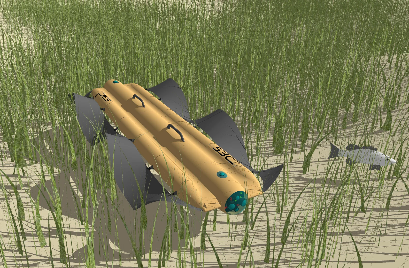
- Looks swag and fishy
Quantitative
-
Tip of fins move 2 inches peak to peak
- Realistic distance we need the fin to move to generate enough thrust in water and enough distance to reach over obstacles on land
- The original goal was 4 inches, but we had to pivot due to geometric constraints. The fin rod pivot point must be at the hull/water interface and the hull must be a certain width for stability in the water.
- CAM follower moves 1 inch peak to peak
-
Camshaft rotates at 60rpm
- Creates a realistic and effective undulating frequency for water and land
Design Features of Main Subsystems
Significant Design Decisions
-
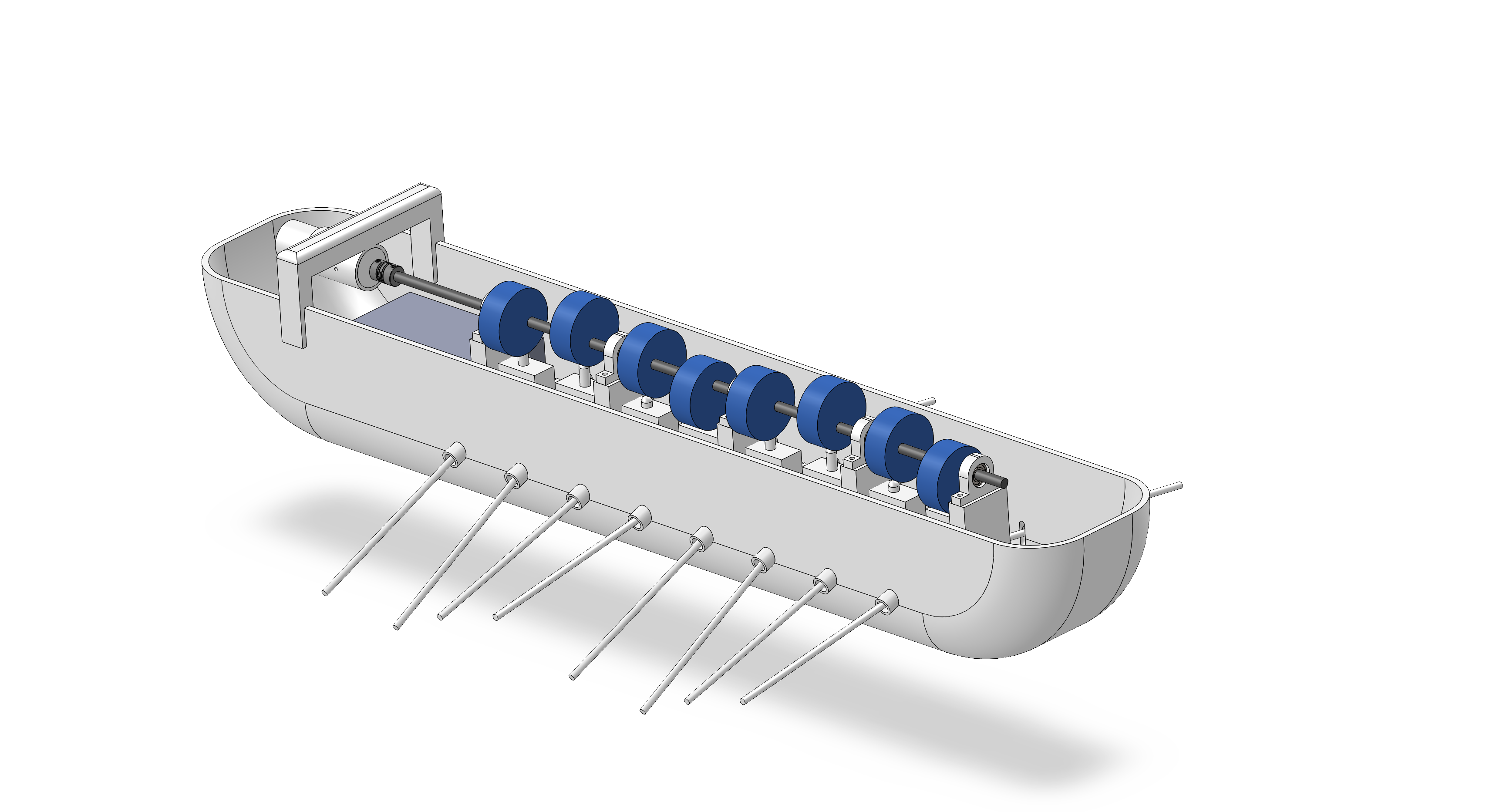
Cam shaft
- We opted for a camshaft to create a simplified version of the more common servo-based undulating fin robot. Using a servo for each fin rod adds control complexity and unnecessary tuning for a mechanical design project. A single central camshaft leads to a more mechanically robust and simple robot.
-
Cam geometry
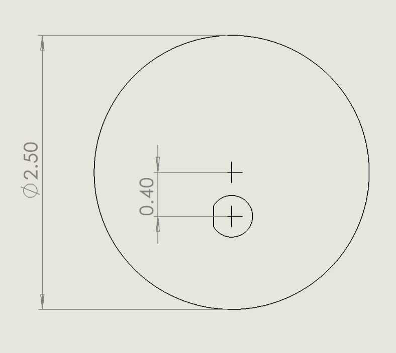
- An eccentric circle CAM geometry was chosen to create the sinusoidal motion for the fins.
-
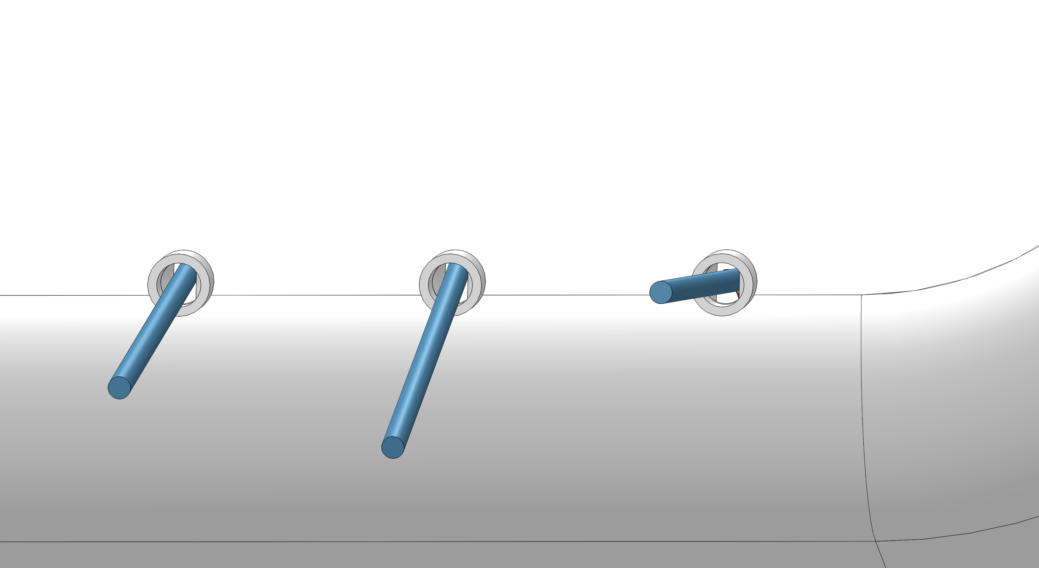
Fin rod pivot geometry
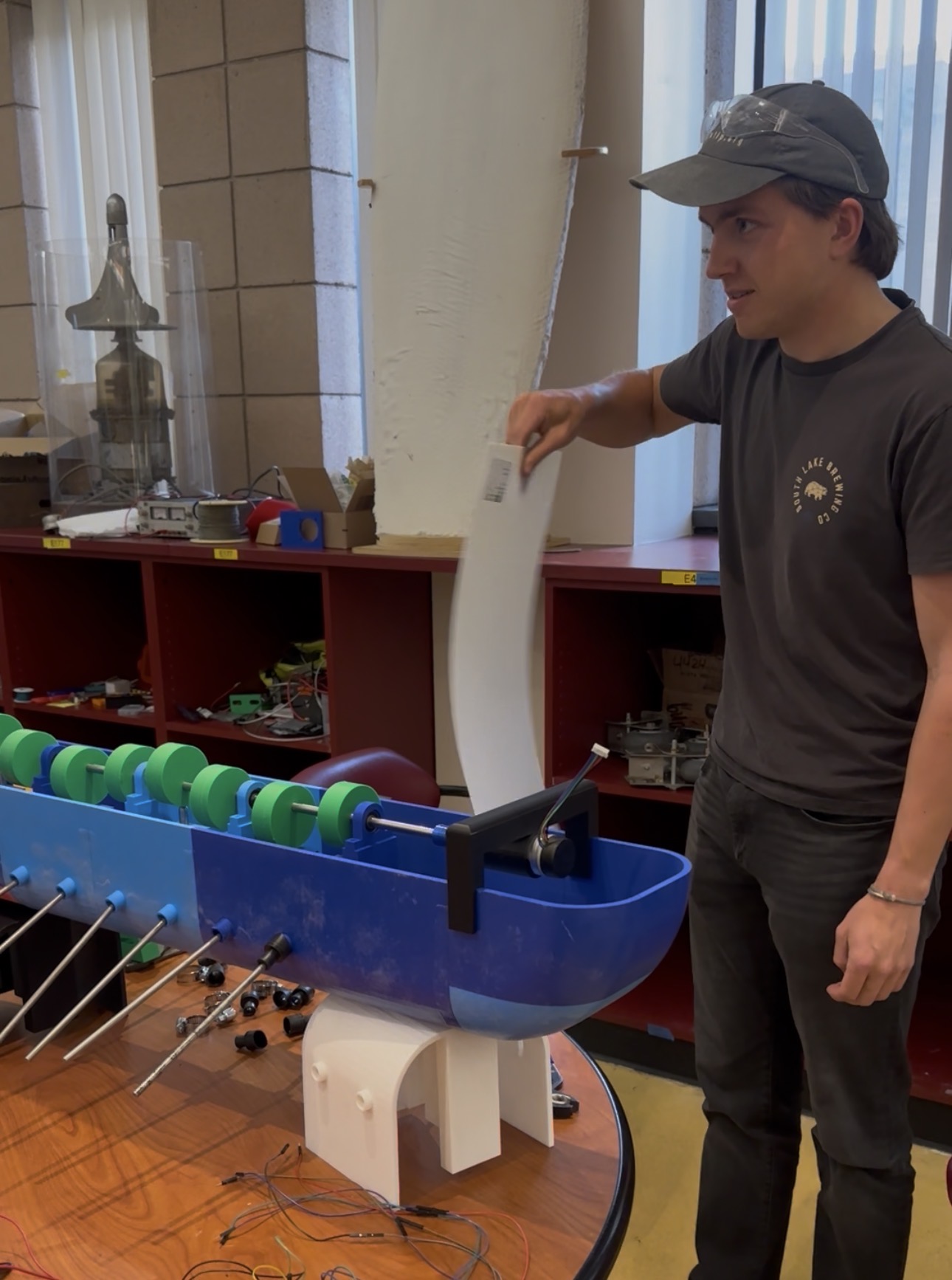
- We designed a slotted hole for the pivot at the hull/water interface that restricts the vertical and horizontal translation of the fin rods while allowing them to pitch back and forth. As shown in the actual physical system, additional waterproofing measures were taken on top of what is shown in the SolidWorks model.
-
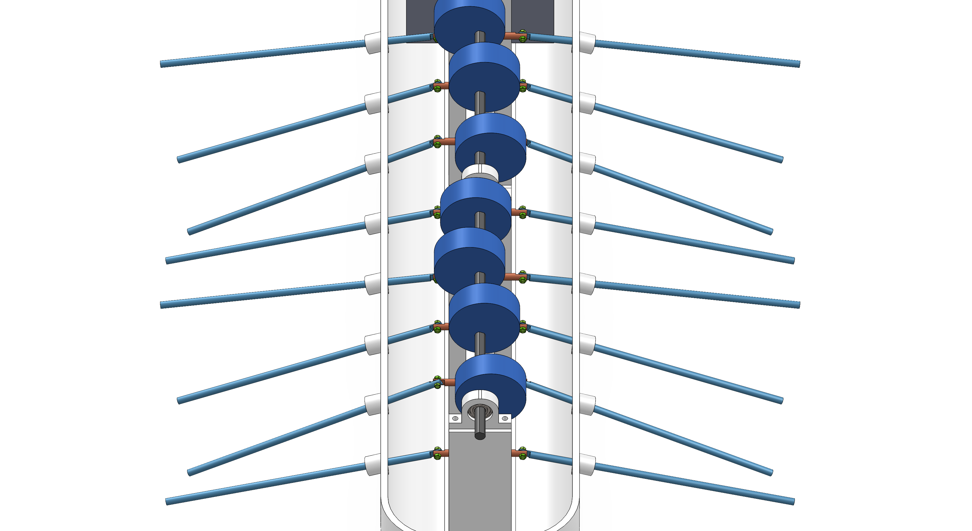
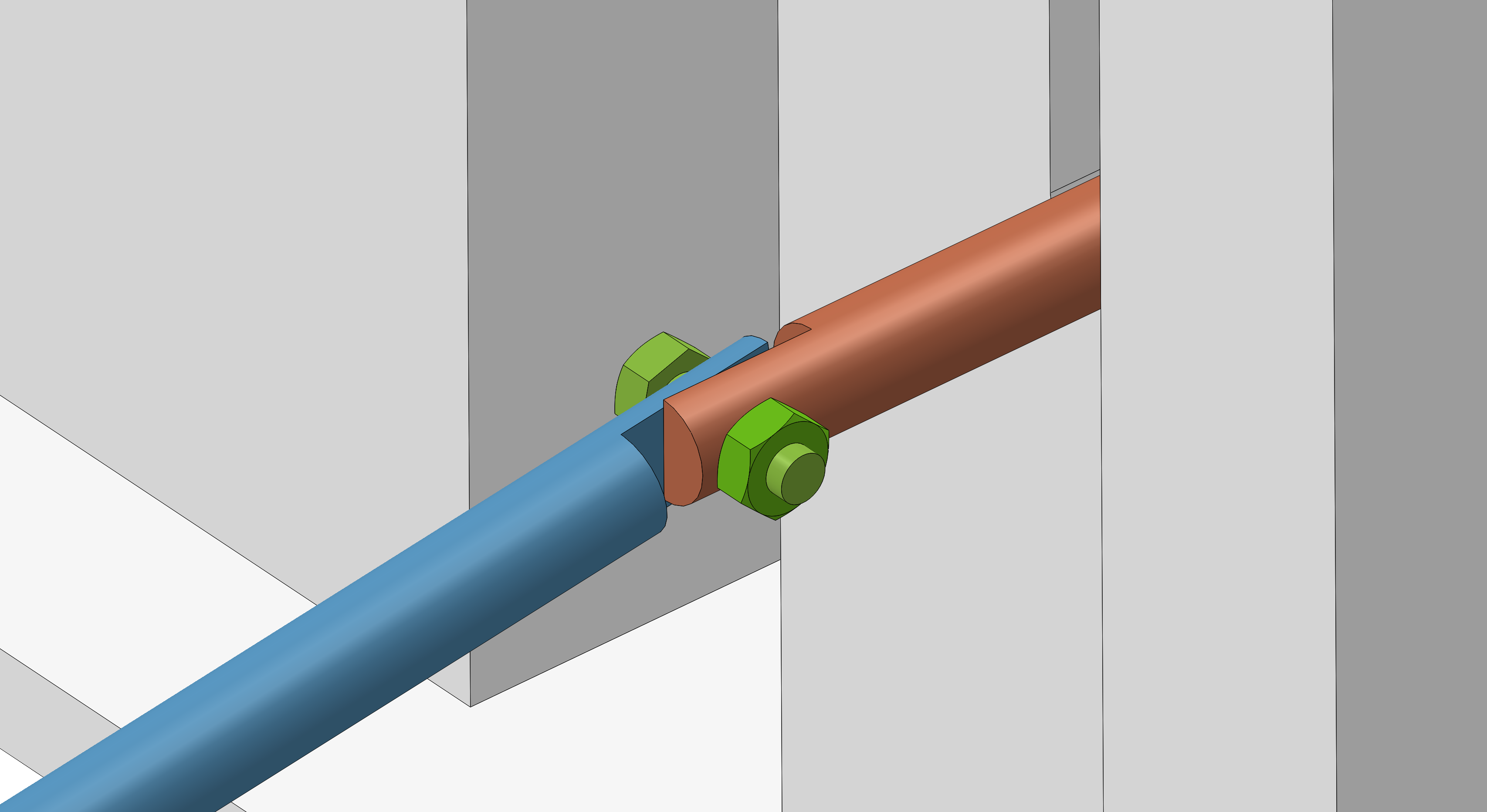
Follower to fin rod connection
- A halved pivot joint was machined to connect the fin rods to the followers.
-
ESP for WiFi control
- A simple ESP32 microcontroller was implemented so that the vehicle can move autonomously over WiFi, taking out the need for long wires to be attached to a separate microprocessor. As shown below, we use an L298N motor driver to drive the 24 VDC gear motor. An LM2596 DC-DC buck converter steps down a 22.2 V 6S LiPo (3300 mAh) battery to a safe input voltage for the ESP32, preventing the on-board regulator from overheating.
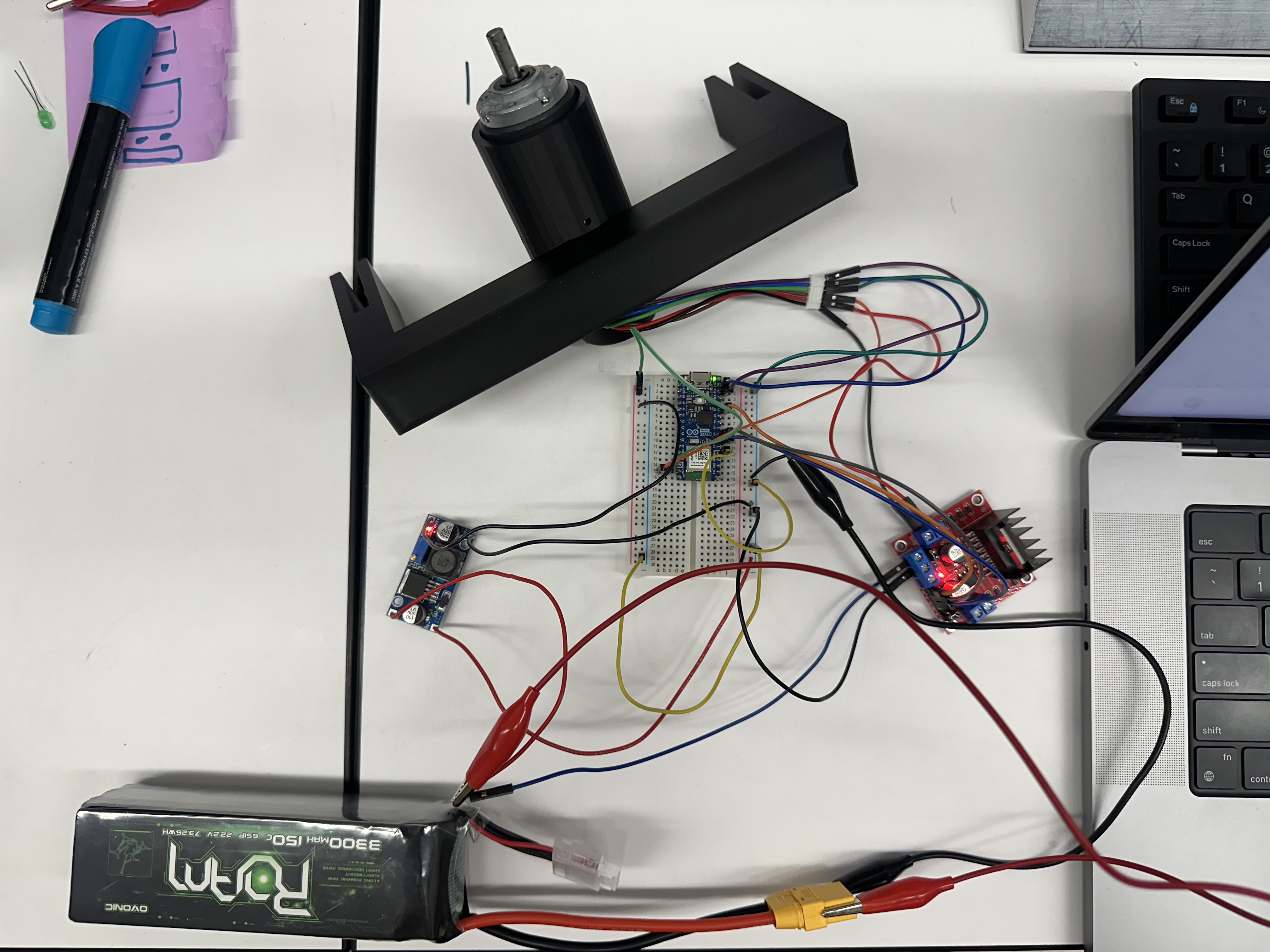
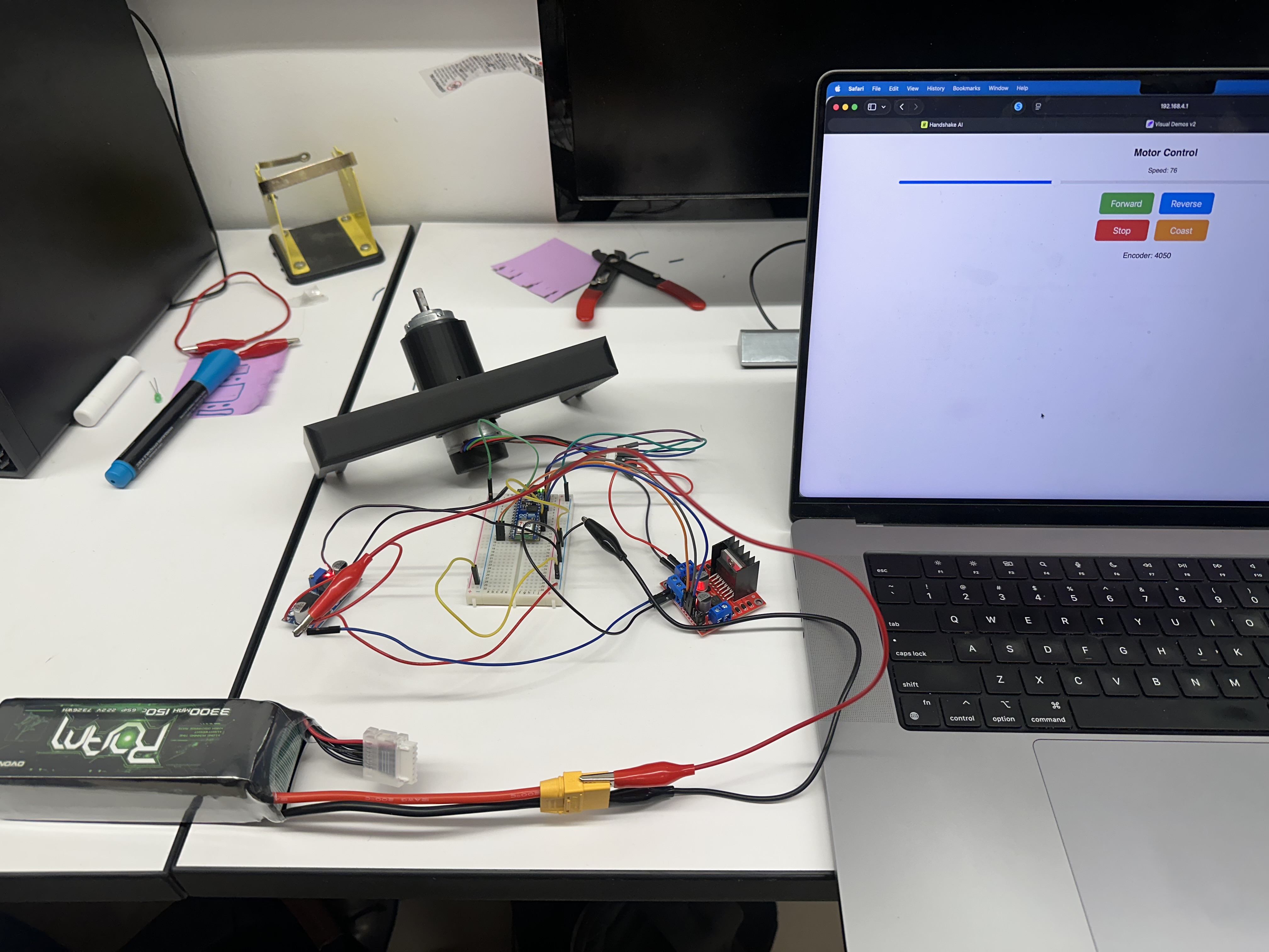
- Implemented as a WiFi Access Point (AP), two modes of motor control are available. First, we can directly set the duty cycle to change the motor speed in classic open-loop PWM fashion. We also calibrated and tuned a closed-loop PID controller on encoder feedback, so the camshaft holds its target RPM despite battery sag and varying mechanical load conditions.
-
Fin rod pivot point location
- Due to size constraints the maximum amplitude of the follower motion was highly limited. To achieve our quantitative specification of 2 inches of fin rod tip motion, the pivot point of the fin rod was strategically placed to create mechanical leverage.
Evaluation of Design
Analysis
CAM MATLAB
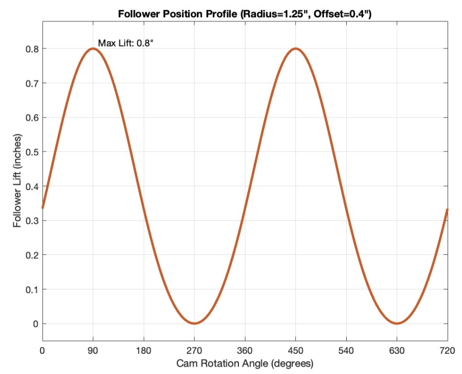
An eccentric cam was chosen as the cam shape to produce a sinusoidal follower motion. The total amplitude of the follower is given by two times the shaft hole offset. The sinusoidal motion of the followers is translated directly to the motion of the fin rods which can be seen in the sinusoidal fin motion. The cams are press fit onto a ⅜″ D-shaft to restrict both axial motion and rotational motion. We utilized a MATLAB script to calculate and plot the sinusoidal motion of the fins.
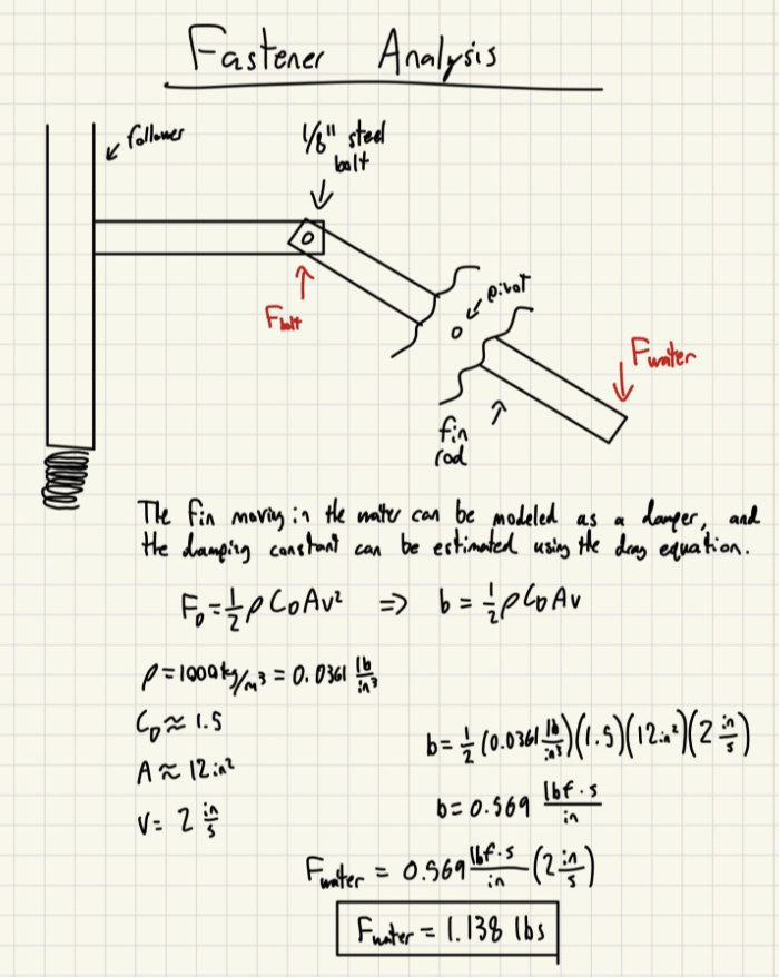
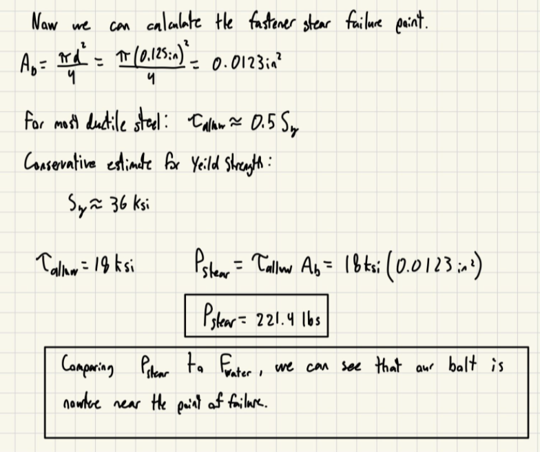
Fastener
In order to demonstrate the feasibility of our fastener choice, we calculate the failure mode for the bolts.
CAM Torque analysis with motor
Finneas’ drive shaft carries 8 eccentric circular CAMs that lift 8 spring-loaded followers. To verify our design before production, we had to verify two things:
- Kinematics: the follower travels the distance at the speed and acceleration that is expected.
- Drive torque: the motor at 60 RPM can supply the average and peak torque needed to spin all 8 of the CAMs against the spring force and friction.
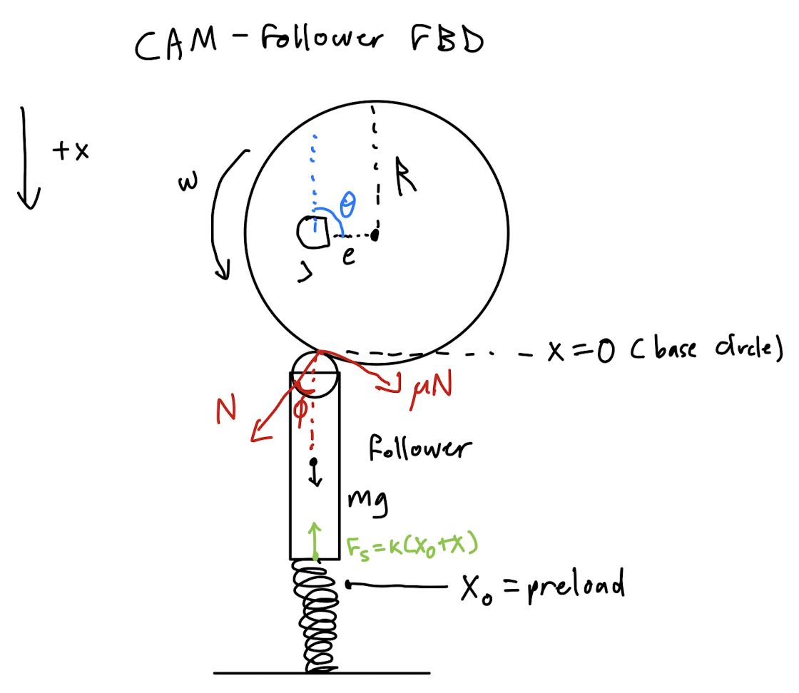
Free Body Diagram
Inputs
| Symbol | Value |
|---|---|
| $R$ | 1.25 in |
| $e$ | 0.40 in |
| $s = 2e$ | 0.80 in |
| $n$ | 60 RPM |
| $\omega = 2\pi n/60$ | 6.28 rad/s |
| $N_\text{cam}$ | 8 |
| $\Delta\phi$ | 90° |
| $m$ | 0.084 lbm |
| $k$ | 2.8 lbf/in |
| $x_0$ | 0.10 in |
| $\mu$ | 0.25 |
| $g$ | 386.09 in/s² |
Our sign convention as shown in the FBD is that $x$ is the lift of the follower, which is measured downward from the minimum-lift position (CAM is barely pushing). Because the CAM sits above the follower and pushes it down, gravity acts in $+x$ (down).
Kinematics
For an eccentric circular CAM with a follower where the contact stays close to the follower’s centerline, the lift is simply the standard simple-harmonic profile:
Now the peak values:
The pressure angle is the angle between the CAM-surface that is normal to the contact point and the direction of motion of the follower:
At 90 degrees ($\theta = 90^{\circ}$) this is largest:
We get $\phi_{\max} = 18.7^{\circ}$, which is well within the bounds for translating roller / knife-edge followers (ours is just a rounded rod). Therefore, there is no risk of excessive side-load or jamming as the follower is guided.
Force analysis
We use the FBD and Newton’s second law on the follower with $+x$ down:
Solving for $N\cos\phi(\theta)$ with $F_{s} = k(x_{0}+x)$ substituted:
$N\cos\phi$ peaks when $\theta = 180^{\circ}$, which is max lift and spring compression, so $\cos\phi = 1$:
The minimum occurs when $\theta = 0$, $x = 0$, and again, $\cos\phi = 1$:
Finally, $N_{\max}$ is the design load for the contact stress of the CAM-follower which we found to be 2.43 lbf.
Drive torque
For each CAM, the instantaneous shaft torque from the contact force can be found using the instantaneous power balance equation below:
Adding a friction term at the CAM-follower contact that opposes the shaft rotation, the moment arm becomes equivalent to the contact-point radius which is $R - e\cos\theta$:
The first term conserves energy, as the spring stores energy as the follower pushes down on it and returns it as the follower springs up. The average over one full revolution is 0, with its peak being:
The friction term is always positive and dissipates energy. When we use the mean normal force from the difference between min and max normal force:
Now, with all 8 CAMs in our design, the 90° phasing between adjacent CAMs (meaning we have four distinct phases with 2 CAMs each), the first and second harmonics of the torque term that conserves energy ($T_\text{cam,peak}$) cancel when added across the four phases. Therefore, the net shaft torque is dominated entirely by friction:
We can find drive power:
Our IG32 24 V geared DC motor covers this margin of requiring 3.3 lbf·in almost right at the mark. We looked online for motor specs as we scavenged this motor, and we found values of similar motors made by the same manufacturer to be anywhere from 3.2 to 5 kgf·cm, which is 2.8 to 4.3 lb·in. Therefore, we were able to be sure that our motor can handle the shaft torque at a small margin. This was confirmed during testing and deployment.
Future Work
- Two camshafts to allow for steering
- More machined components to allow for higher torque
- Sensors for more robust control and various tasks
- Fin rod adaptations or additional tilt motors that allow it to work at different angles (such as pointing straight down for land movement or optimizing movement based on environment)
- Non-PLA hull for better waterproofing
- Fully enclosed hull to allow diving
Conclusions
Finneas the Undulator met the desired requirements and specifications. Finneas moves in water and on land, is waterproof, floats, and looks swag and fishy. Not only this, but the tips of the fins move ~2 inches peak to peak with a corresponding CAM follower movement of ~1 inch peak to peak. The camshaft rotates at differing speeds based on a quickly configurable, web-browser PWM controller, also allowing it to reverse and move backwards. A closed-loop PID controller was also implemented to maintain the desired RPM. The team achieved their learning goals, especially gaining valuable experience maintaining CAD models, using an unconventional locomotion mechanism, manufacturing different components in modular, reasonable ways, waterproofing, and performing detailed analysis to verify outputs.
Thank you for visiting our website! Have a great rest of your day :)
Team